I wanted to build the best robotic arm I could out of hobby servos — no exotic actuators, no $400 Dynamixels, just the same $8–$25 servos everyone already has a drawer full of. The bottleneck turned out not to be torque, or speed, or even the servos themselves. It was math.
Every hobby-servo project I’d seen — including my own earlier one, Servo Calibrator — points the shaft with the same two numbers: a minimum pulse width, a maximum pulse width, and a straight line drawn between them. Command 90°, get roughly 1500µs; command 45°, get roughly 1125µs. It’s the formula in every tutorial, every library, every datasheet’s “quick start.” It’s also, it turns out, quietly wrong — and the wrongness isn’t random. It’s a real, measurable, servo-specific curve that a straight line simply can’t capture.
So I built a bench rig — an Arduino, an AS5600 magnetic encoder riding on the output shaft as ground truth, and a Python driver that could sweep, measure, and grade any servo I threw at it — and set out to answer one question with actual data, not vibes: how much accuracy is that straight line actually costing me, and is it worth fixing?
The fix itself isn’t exotic — it’s a lookup table. Instead of one straight line from min-pulse to max-pulse, sweep the real servo across its full range, record the actual angle at a bunch of pulse widths, and interpolate between the two nearest real measurements instead of trusting a formula. This obviously works in principle. What I wanted to know was how much it’s worth, in real degrees, on real hardware, across more than one servo — because a result from a single unit could just be that unit having a bad day.
The bench
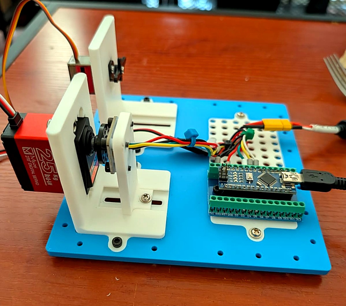
The actual rig, one unit at a time: a Miuzei 25kg Servo with the AS5600 mounted on it on the left, an MG90D on the right, an Arduino Nano (CH340 clone) doing the driving.
Nine servos, three families — a Miuzei 25kg Servo, a knockoff MG996R, and an MG90D, three units each — went through the same protocol: a direction-averaged fine sweep against the AS5600 as ground truth, then thousands of independent accuracy trials. Every trial picked a random target angle and a random model independently, computed that model’s predicted pulse, physically commanded it, waited a full second, and measured the real resulting angle. Target and model are drawn independently on purpose — an earlier pass through this data paired them, and it quietly let a bad model borrow a good model’s positioning within the same round. Decoupling them was the difference between a flattering result and a true one.
55,029 independent trials, six models compared per servo (the naive 2-point linear formula, plus 10/20/30/40/50-point lookup tables), across every unit — not a residual against the calibration curve that produced the table in the first place.
Everything below is the pooled, family-level view. If you want the unabridged version — every unit’s own range-finding sweep, calibration curve, backlash, and accuracy, not averaged together — the full dataset has all of it.
Mean error vs. model complexity, pooled across all nine servos
Grand mean absolute error across all nine units, six models, 55,029 independent physically-measured trials.
The cliff happens once, between the naive formula and the first real table. After that, the line is flat — table50 is within noise of table10, on every family, every time. If you’re storing this on an ATmega with 2KB of RAM, that’s good news: you don’t need fifty points of precision to get fifty points’ worth of accuracy. Ten to twenty is the whole win.
The penalty isn’t the same for every servo
Averaged per family, the naive formula’s mean error is 0.87° for the Miuzei 25kg Servo, 1.16° for the knockoff MG996R, and 1.97° for the MG90D — more than double the Miuzei’s. The MG90D’s calibration curve simply bows further from a straight line than the other two designs do; on one individual unit its naive error hit 2.75°. For that servo, a lookup table isn’t optional insurance — it’s the difference between a servo that behaves linearly and one that doesn’t.
| Family | Naive (linear2) | Calibrated (table20) | Backlash (mean) | Lost in testing |
|---|---|---|---|---|
| Miuzei 25kg Servo | 0.87° | 0.40° | 1.17° | 0 of 3 |
| Knockoff MG996R | 1.16° | 0.31° | 1.03° | 2 of 3 |
| MG90D | 1.97° | 0.57° | 1.33° | 0 of 3 |
The knockoff MG996R deserves its own aside: once calibrated, its accuracy is the best of the three families (as low as 0.18° on one unit) — but two different physical units died mid-study, both from encoder-freeze failures that took the motor with them. The study’s original plan was even an 8-hour accuracy phase; the very first candidate tested — a knockoff MG996R — died about 3.5 hours in, which is why every unit after it ran a 3-hour standard instead, and a second knockoff MG996R later died 61 minutes into that standard, which is why this family alone now runs on a 1-hour cap. If you build with these: budget for spares.
The servos aren’t built the same, mechanically
Accuracy wasn’t the only thing this bench measured. Every unit’s full range-finding sweep and fine calibration sweep also produced two more numbers worth knowing before you design around one of these: how much pulse width actually buys you a degree of rotation, and how much backlash — the gap between approaching an angle from above versus below — a static calibration table can’t touch at all.
Pulse width required per degree of rotation, by family
All nine units were swept across a similar ~1.6–1.8ms pulse span. The knockoff MG996R needs ~46% more of it per degree of real rotation than the other two families — a real gearing difference, consistent across all three of its own units, not a calibration artifact.
The gearing difference matters for planning a build (a narrower pulse span buys less usable range on the MG996R), but it’s a separate question from backlash — the up-sweep and down-sweep of the same fine calibration disagreeing at the same commanded pulse, purely from mechanical slop in the gear train. A lookup table stores one angle per pulse; it has no way to represent “depends which direction you came from,” and can’t fix this even in principle.
Backlash: mean vs. worst-case disagreement, by family
Up-sweep vs. down-sweep disagreement at shared pulse values, from the same fine calibration sweep that built each unit's ground truth. The MG90D—already the servo whose curve bows furthest from a straight line—also has the most backlash, on average and at its worst.
It’s not a coincidence that the MG90D leads both charts in this section as well as the accuracy table above it: whatever makes its mechanism less linear also tends to make it looser. None of that shows up in a lookup table’s numbers directly, but it’s exactly the kind of thing a table can’t fix — if a build’s joints need to settle to a repeatable position regardless of approach direction, that’s a mechanical design problem (a hard stop, a spring preload, a consistent single approach direction in software), not a calibration one.
Why a single joint can shrug off a degree, and an arm can’t
A pan/tilt camera mount can absorb a degree of error and nobody notices the horizon tilt. A robotic arm can’t — every joint’s error doesn’t just sit there, it rides on top of every joint downstream of it, compounding into wherever the end effector actually lands.
End-effector drift radius: naive linear model vs. calibrated table, three-joint arm
Three joints × 120mm links, this study's average angular error — order-of-magnitude estimate, not a full kinematic stack-up. Both circles show a radius, not a diameter: the distance from the commanded point to where the end effector actually lands, not the width across the uncertainty region.
Take a modest three-joint arm — shoulder, elbow, wrist, each riding on a 120mm link, well within reach of servos this size. Run this study’s average numbers through it: the naive straight-line formula puts roughly 2.8mm of drift on the end effector from each joint’s error, on its own. Stack three of them and a build commanded to hit an exact point can land more than 8mm away from where you told it to go — enough to miss a socket, misplace a component, or draw a line that visibly isn’t straight.
Swap in a 20-point calibration table built from the same kind of sweep this study ran, and each joint’s error drops from ~1.3° to ~0.4° — cutting that same three-joint arm’s drift to roughly 2.7mm. That’s the difference between an arm whose accuracy is limited by its own math, and one whose accuracy is limited by the thing that should actually be limiting it: backlash, structural flex, and how tightly it was built.
So, what’s the best arm I can build?
Bench-tested and totaled up: run through a 10-to-20-point calibration table instead of the textbook formula, the Miuzei and the knockoff MG996R both land within half a degree of their commanded target — sub-millimeter positioning on a typical hobby-arm link. The MG90D lands a little behind that, at 0.57° — just over a millimeter at the same link length — but that’s still a huge jump from its naive 1.97°, just not quite sub-millimeter. Either way, that’s not a marginal win worth shrugging off; it’s the difference between a robot arm that reaches roughly where you tell it to, and one that actually lands there.
Which family to build with comes down to reach, load, and how many spares you’re willing to keep on a shelf, not whether it’s worth calibrating — on this bench, that was never really in question. The Miuzei is the steady, reliable default for a base or shoulder joint. The MG90D is small, cheap, and needs the table most, which makes it a strong pick for a wrist or gripper specifically because calibration erases its biggest weakness. The knockoff MG996R has the best calibrated accuracy of the three, but earned its reliability caveat honestly — keep spares.
Calibrate your own servo
You don’t need this bench to get this result on your own servo. Everything above runs through Servo Calibrator, a free browser tool built from this same study: wire up an AS5600 breakout and any Arduino — a few dollars in parts, nothing exotic — flash one sketch, then click a single Calibrate button. It stall-scans the servo’s real mechanical range, sweeps it twice, and builds a direction-averaged 20-point table automatically, usually in well under a minute. No protractor, no spreadsheet, no manually stepping through pulse widths by hand.
A table alone only fixes where the servo ends up — it says nothing about how it gets there. That’s a separate problem: Universal-Trajectory-Interface, the trajectory-planning library that Servo Calibrator’s own firmware already uses to drive smooth, speed-and-acceleration-limited moves against your table instead of snapping straight to the target.
Comments
Name and comment are public. Email is never shown or shared — it's only used if I need to follow up. New comments are held for review before they appear.
Loading comments…